Mini Electrical Final Assembly Workflow
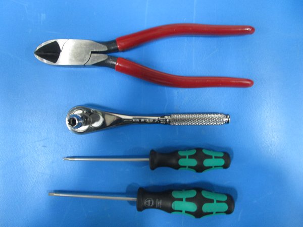
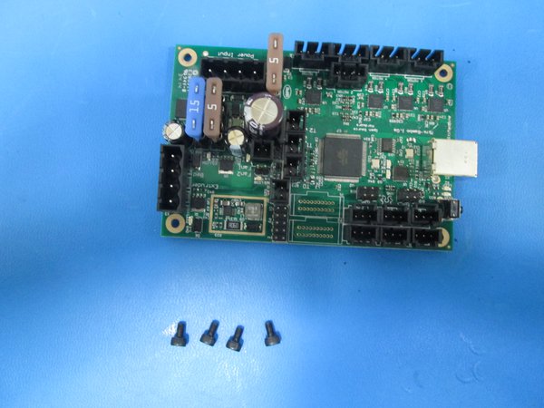
Tools
- Are all the tools and components gathered?
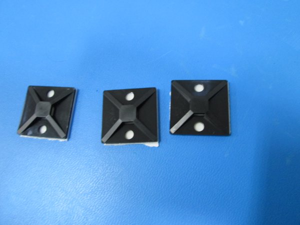
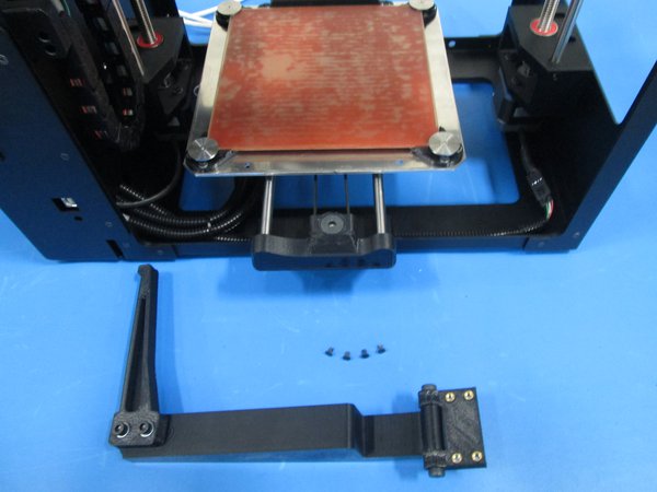
Attach Tie Bases.
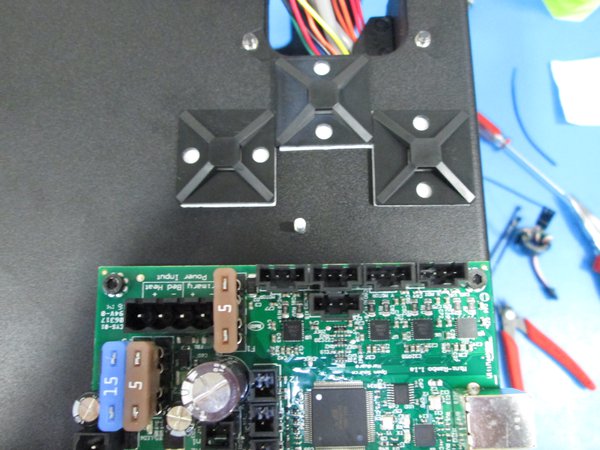
Place Bases on frame.
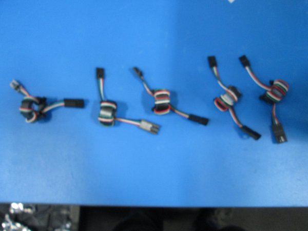
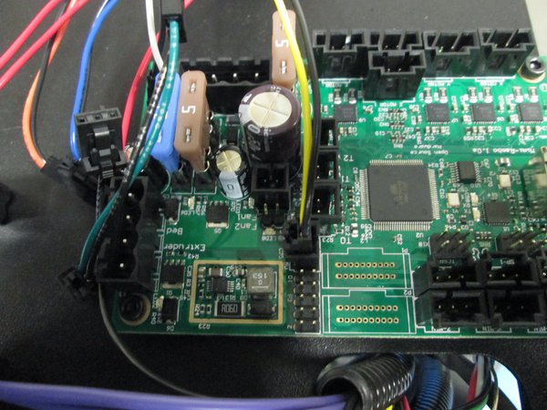
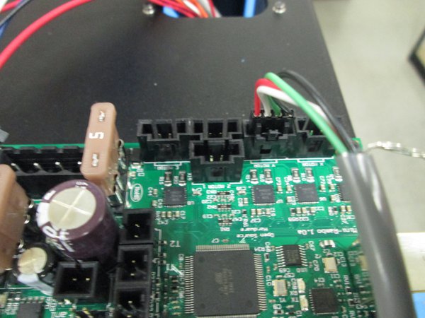
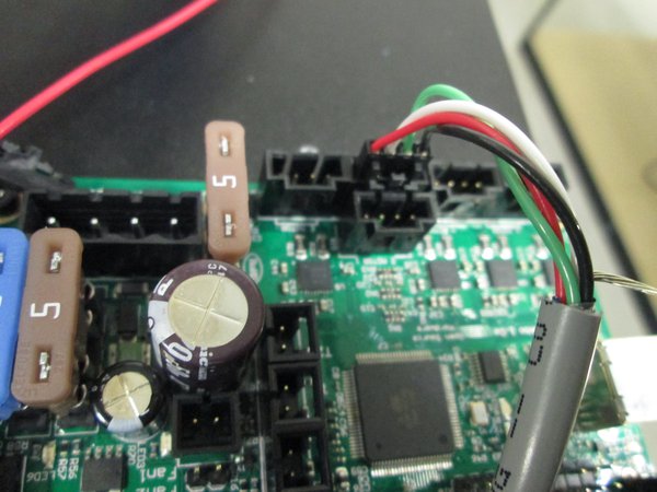
Gather Five ferrite jumpers.
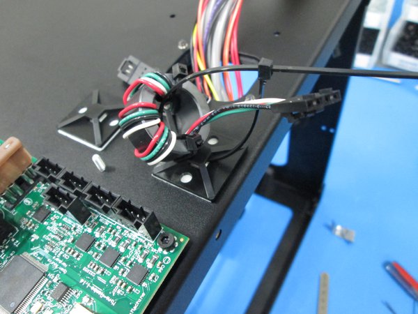
Attach ferrite number one to far right tie base.
Attach ferrite number four to far left tie base.
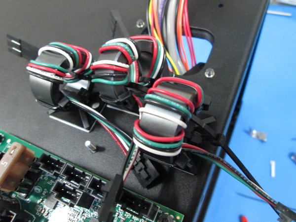
Attach ferrite number two to far right tie base.
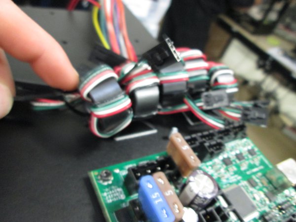
Attach ferrite 3 and 5 to left tie base.
Add three tie bases for ferrite jumpers and white ferrite.
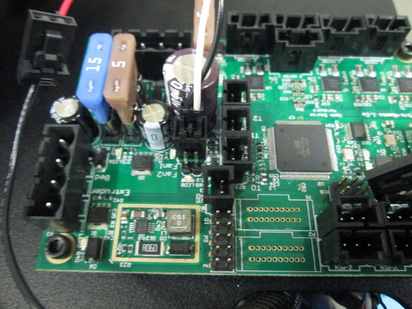
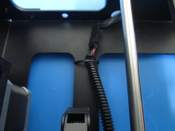
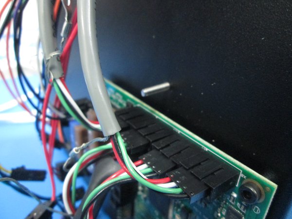
Make sure on ferrite jumper the male end is facing the top.
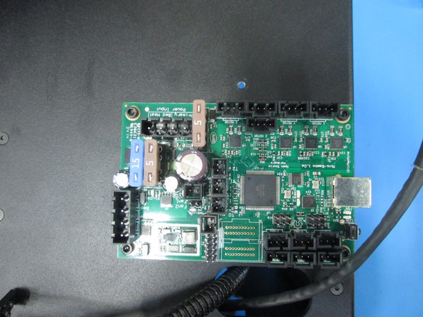
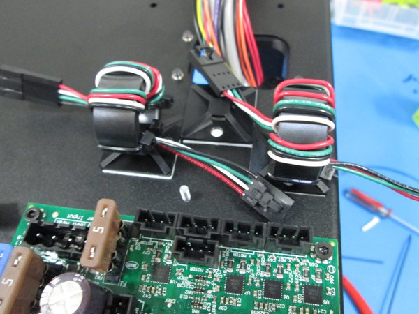
Female ends will plug into rambo.
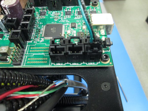
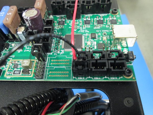
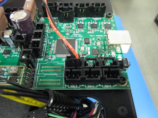
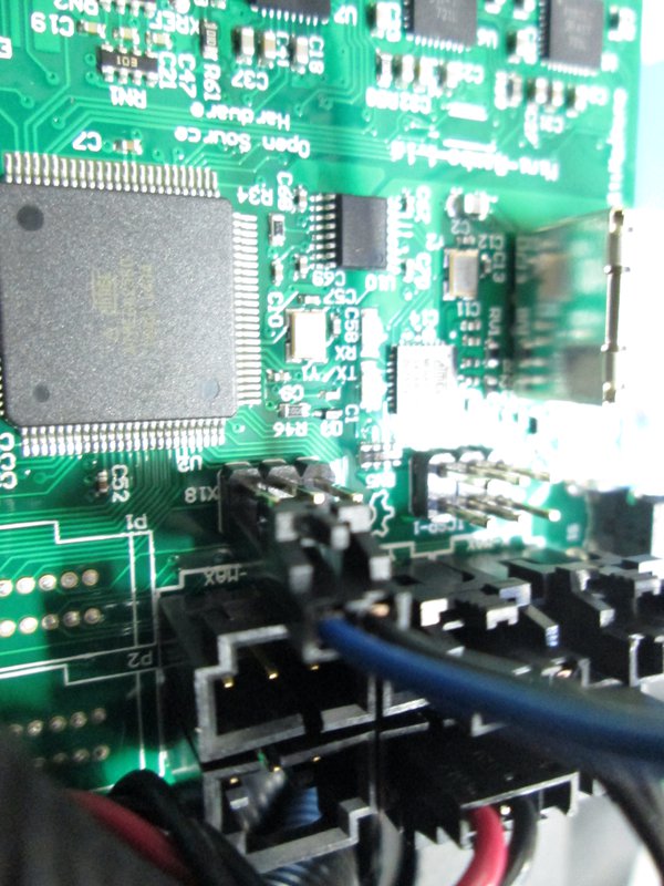
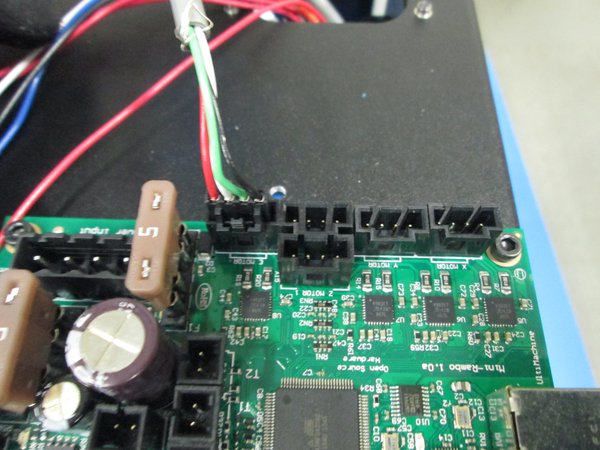
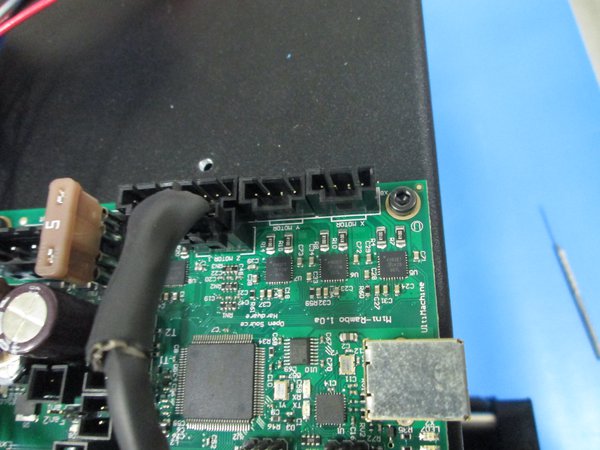
Ferrite number one, the furthest to the right will plug into the X-motor slot on Rambo.
Ferrite number four will plug into the Z-motor slot on the Rambo. (Either Z-motor slot will work.)
Ferrite number two will plug into the Y-motor slot on Rambo.
Ferrite number 3 will plug into the remaining Z-motor slot.
The last ferrite, number five will plug into the extruder slot on the Rambo.
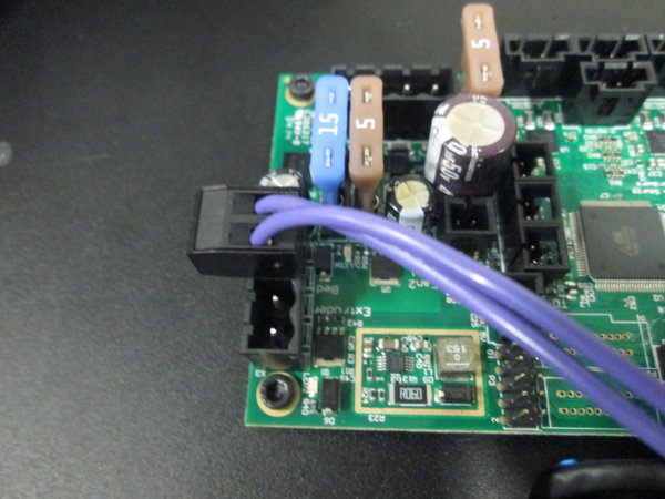
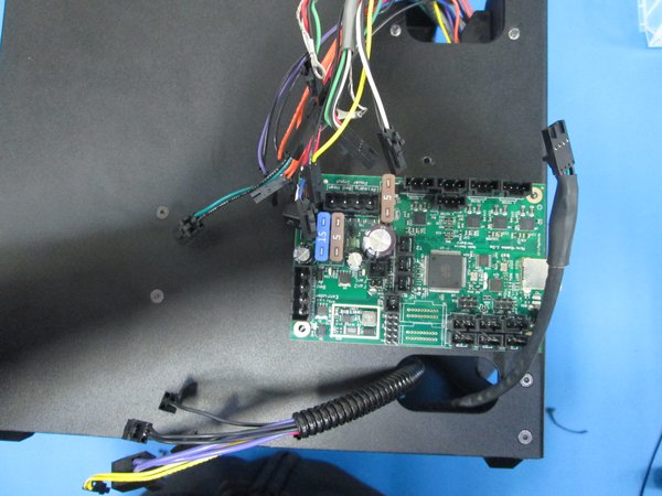
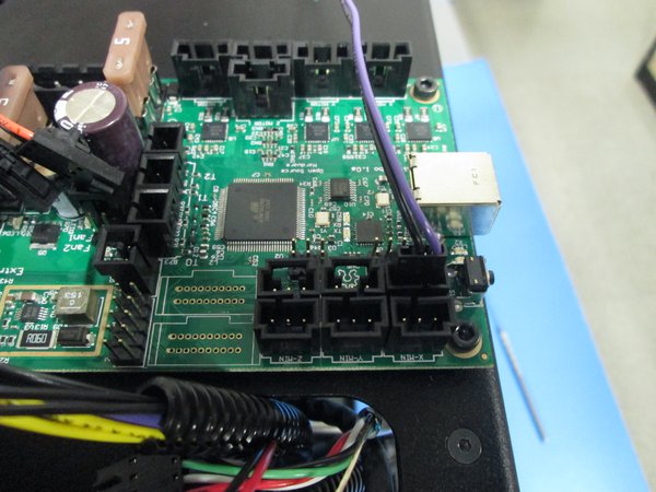
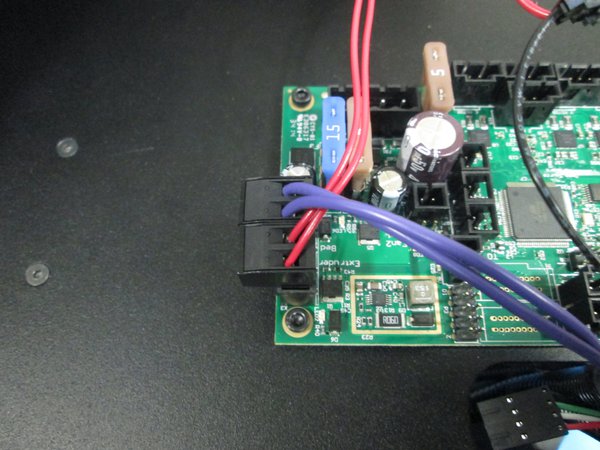
Purple heat bed wire connected
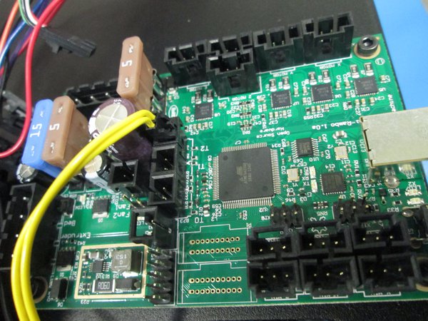
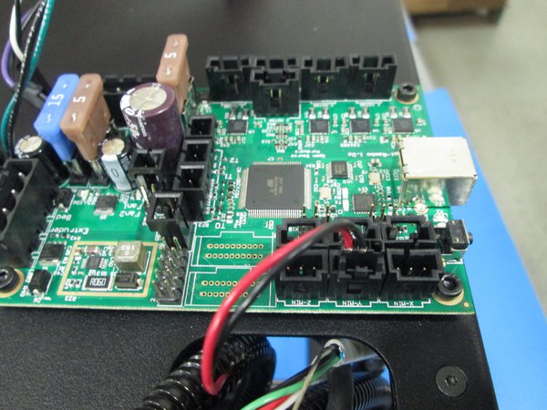
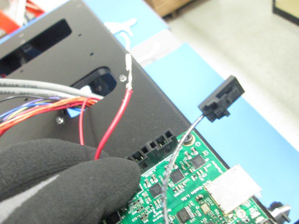
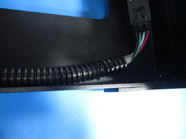
Single red and black wires
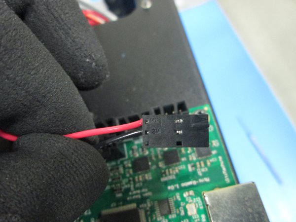
Red wire plugged in
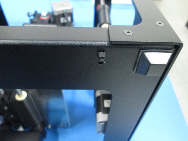
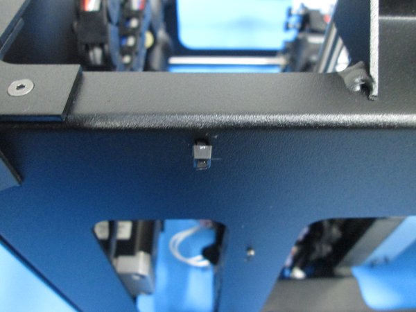
Z min switch location
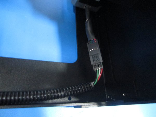
Blue and black Z limit switch location, note orientation

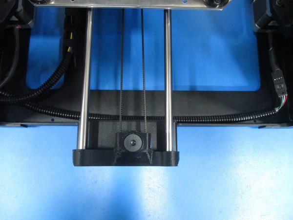
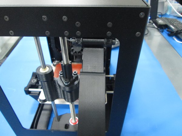
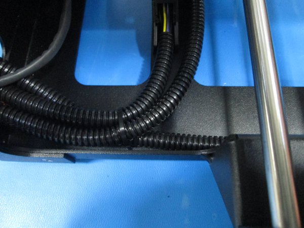
Y motor connected and first zip tie location
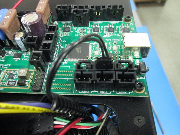
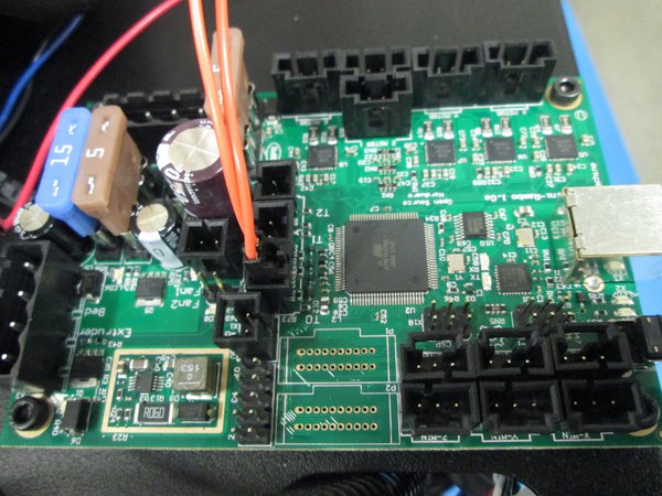
Z motor extension location
From bottom
All three bundles zip tied together
From bottom
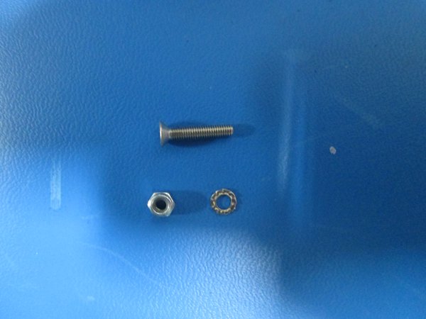
Hardware
Ground post screwed through
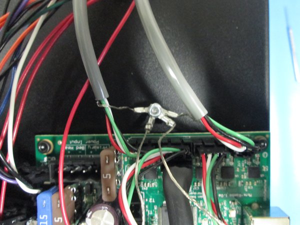
Wires attached and secured
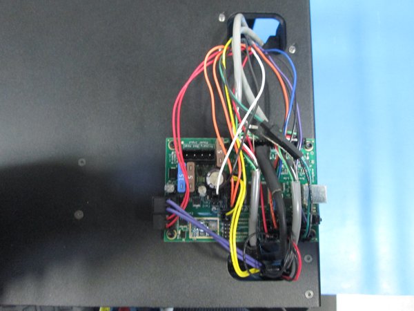
Another view