Mini Print Head Assembly Workflow
Components Required
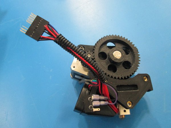
- Extruder Assembly
- Extruder Mount
- Nozzle Assmebly
- Hex mount plate
- M2x6 SHCS
- M2x10 SHCS
- M2 Washer
- M3x12 SHCS
- M3x14 Flat head screw
- M3 Washer
- M4x20 SHCS
- M4 Washer
- 40 mm Fan
- Fan Mount
- Limit Switch
- Black and purple limit switch wires
- Blower Fan
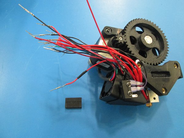
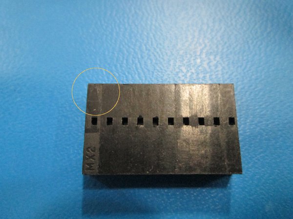
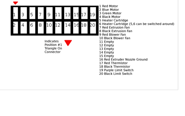
- 20 POS connector
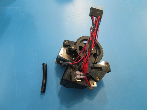
- 75 mm Panduit
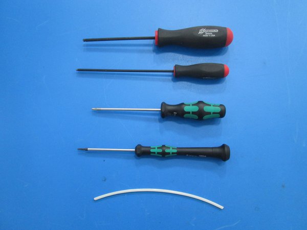
Tools Required
- 1.5 mm Allen driver
- 2 mm Allen driver
- 2.5 mm Allen driver
- 3 mm Allen driver
- Piece of filament
- Are all the tools and components gathered?
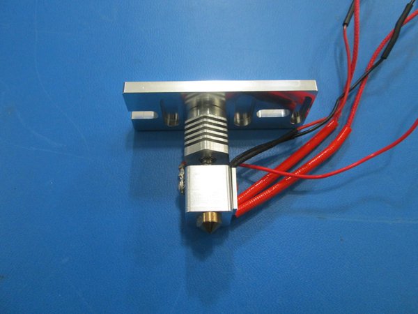
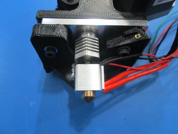
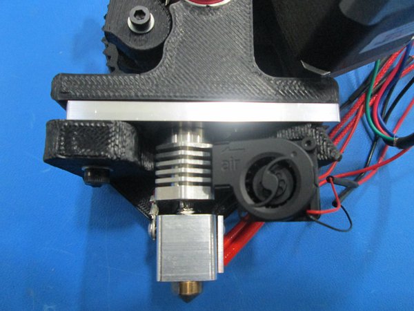
Place the hex mount plate onto the nozzle as shown.
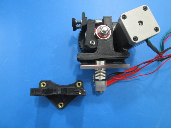
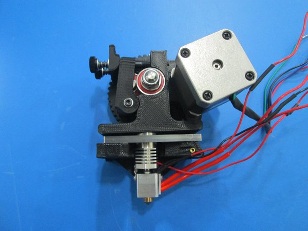
Sandwich the hex mount in between the extruder mount and the extruder body as shown making sure all the wires are to the back and right.
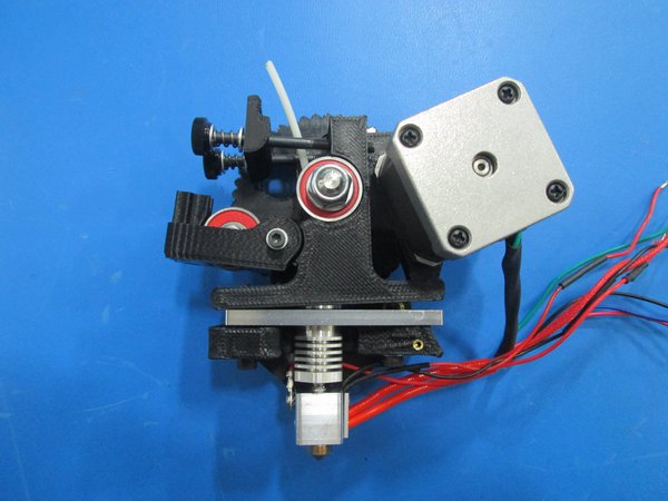
Slide a piece of filament through the body and into the nozzle to ensure alignment.
Using 2x M4x20 SHCS and M4 washers secure the extruder mount, nozzle, and body together.
Make sure the heater block is aligned straight down evenly as shown.
Pull the piece of filament out making sure it slides through smoothly.
- Does filament slide through?
- Is the nozzle aligned properly?
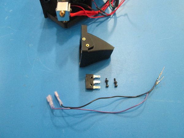
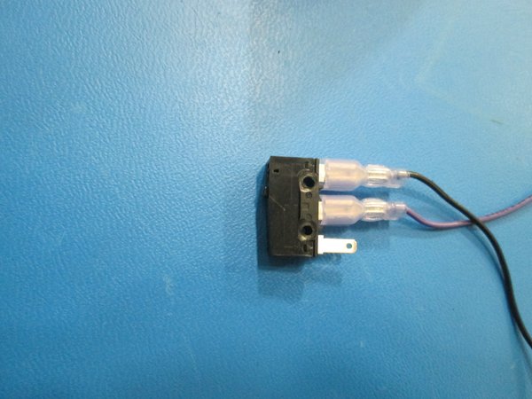
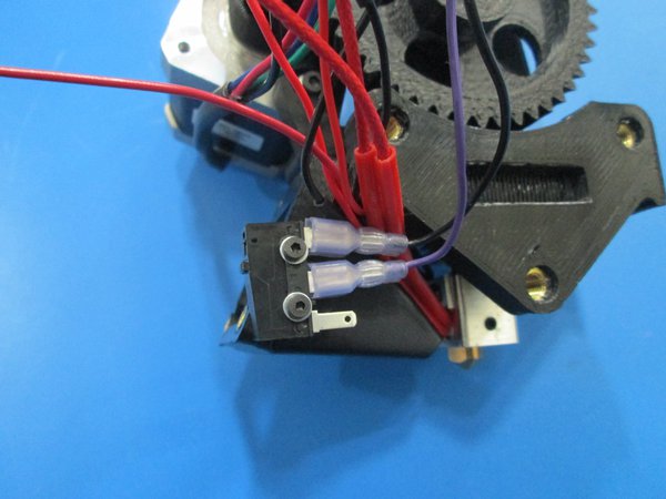
Prep the limit switch by connecting the black and purple wires as shown. Note the orientation of switch and wires in pictures.
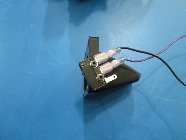
Attach the limit switch to the fan mount using 2x M2x10 SHCS and M2 washers as shown.
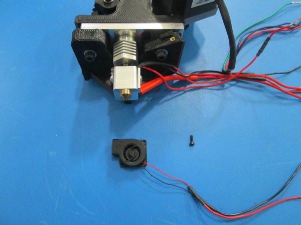
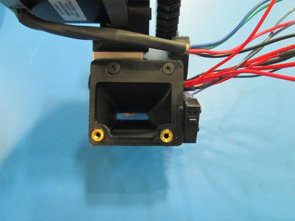
Attach the fan mount to the extruder mount using 2x M3x14 flat head screws as shown, make sure the blower fan wires are tucked under the fan mount, reference pictures.
Make sure not to pinch any wires with the fan mount.
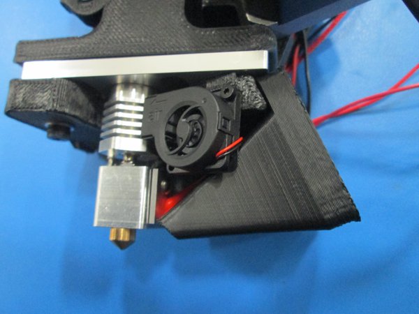
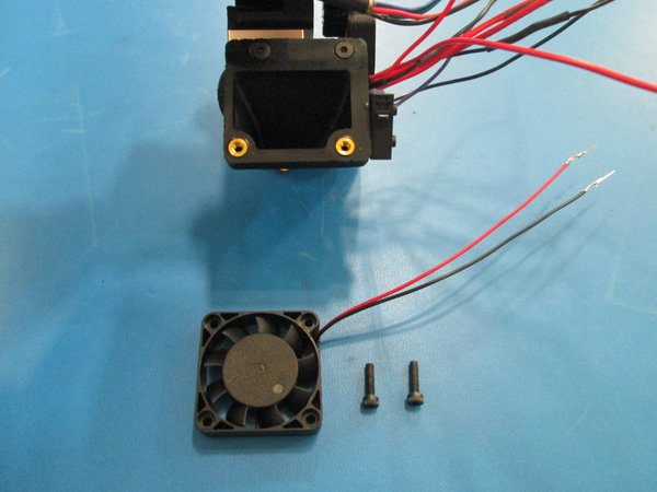
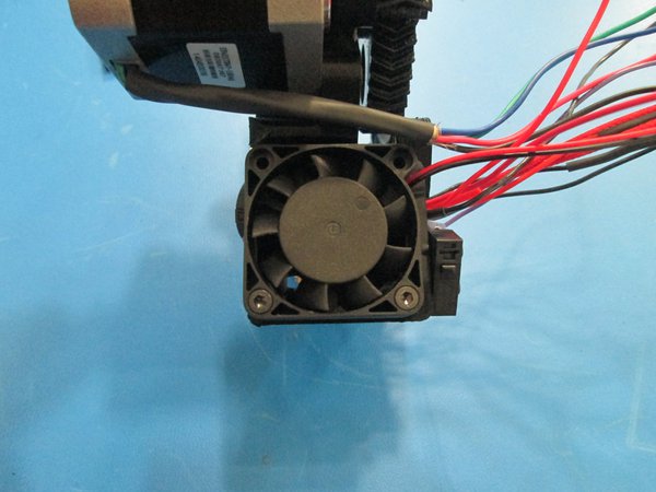
Attach the 40 mm fan to the fan mount using 2x M3x12 SHCS as shown. Note orientation of fan and wires in pictures.
Make sure all the wires are tucked behind the limit switch as shown.
- Are the wires tucked in properly?
- Is the fan mounted correctly?