Mini Mechanical Final Assembly Workflow
Components Required
- Frame
- X End Idler Assembly
- X End Motor Assembly
- Print Head
- X Carriage
- X Carriage Cover
- Smooth Rods
- Belt
- Bed Plate
- Heat Bed
- M3x6 Flat Head Screws
- M3x8 BHCS
- M3 Washers
- M3x16 Stainless Flat Head Screws
- Bed Leveling Washers
- M3x5 SHCS
- M3 Star Washer
- Zip Ties
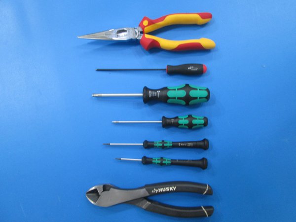
Tools Required
- 1.3 mm Allen driver
- 1.5 mm Allen driver
- 2 mm Allen driver
- 2.5 mm Allen driver
- 4 mm Allen driver
- Cutters
- Needle Nose pliers
- Are all the tools and components gathered?
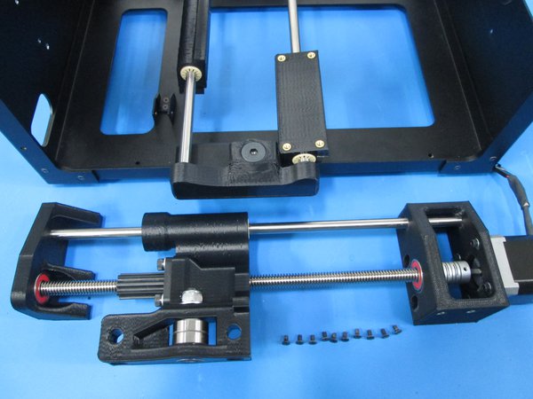
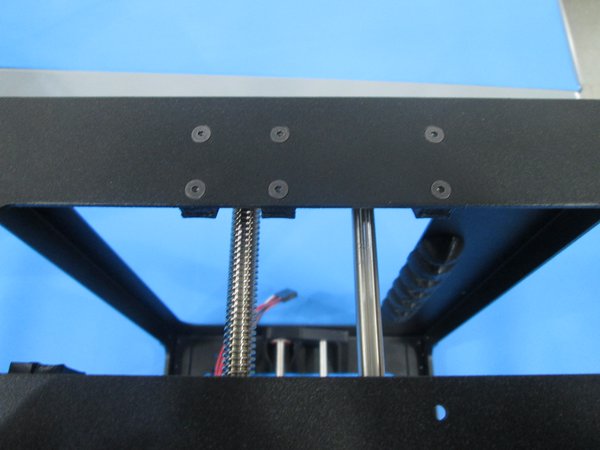
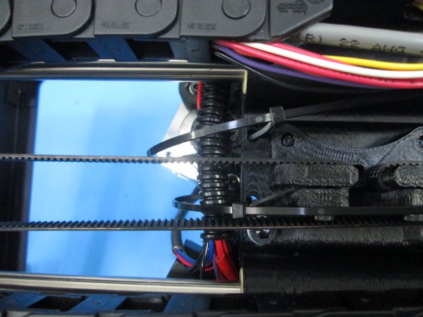
Attach the X end idler assembly to the right inside of the frame using 10x M3x6 flat head screws as shown.
X end idler will come with loose motor, Z-nut and coupler screws, these need to be tightened in a specific sequence.
First tighten the two bottom coupler screws.
Next tighten the four motor screws so it is lined up with the coupler and Z rod.
Last tighten the Z-nut screws so they are snug.
Do Not Use Hand Drill.
Make sure there is 95-100mm of wire is coming out extruder end.
- Next
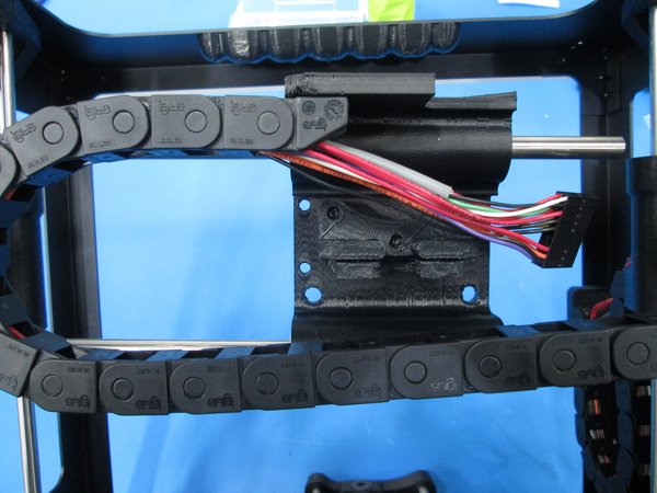
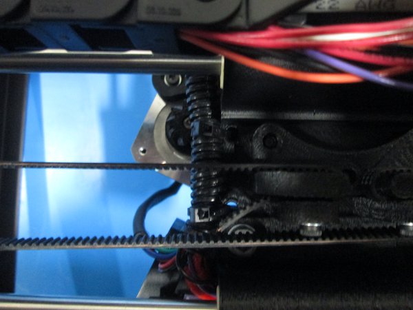
Attach the X end motor assembly to the left inside frame using 10x M3x6 flat head screws as shown.
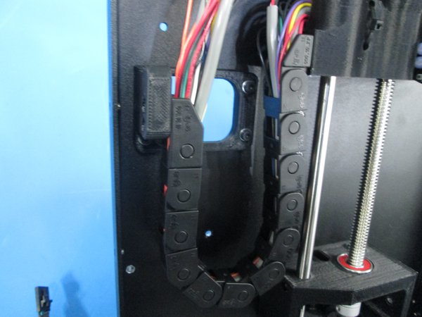
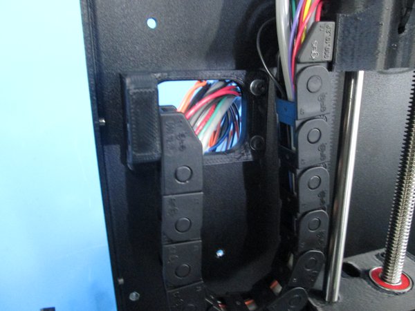
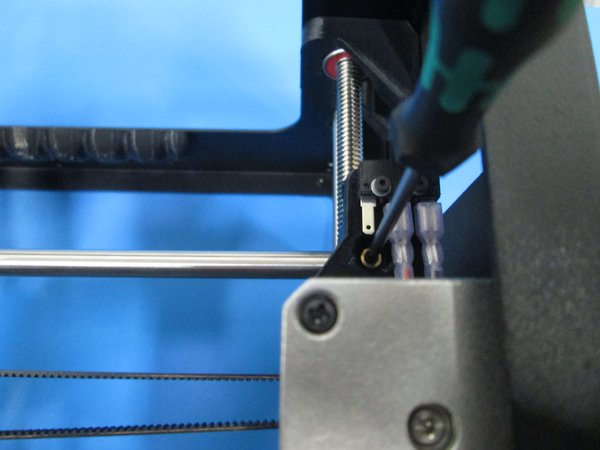
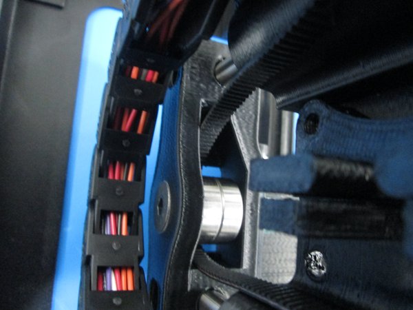
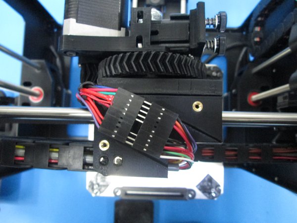
Connect the cable guide to the female cable guide connector making sure you don't pinch any wires as shown.
X end motor drive will come with loose Motor, coupler and Z-nut screws.
First tighten the two bottom coupler screws.
Next tighten the four motor screws so it is lined up with the coupler and Z rod.
Last tighten the Z-nut screws so they are snug.
Route the bundle of wires out of the relief as shown.
- Next
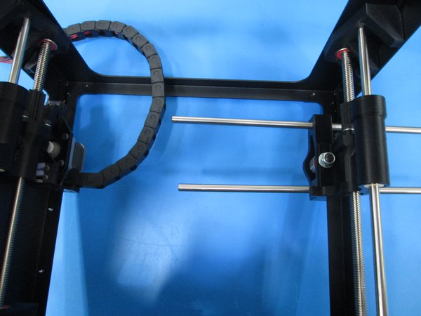
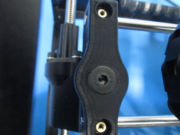
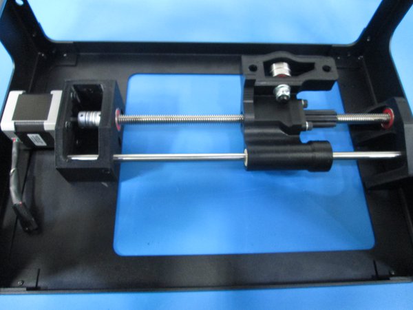
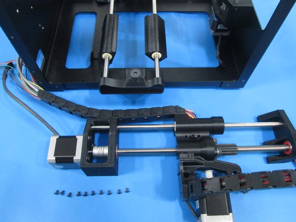
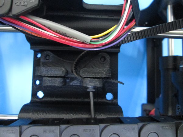
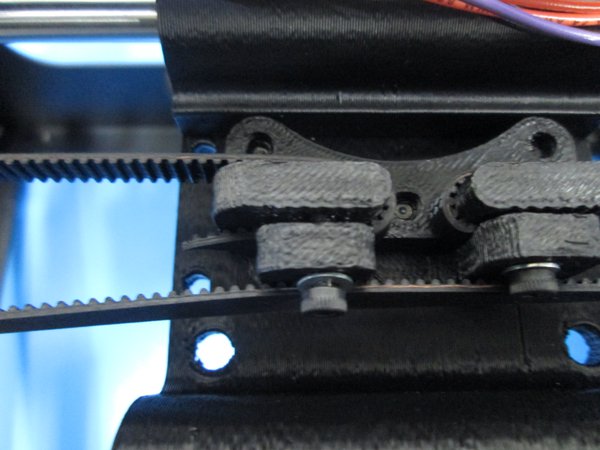
Install 2x smooth rods through the x end idler about half way through as shown.
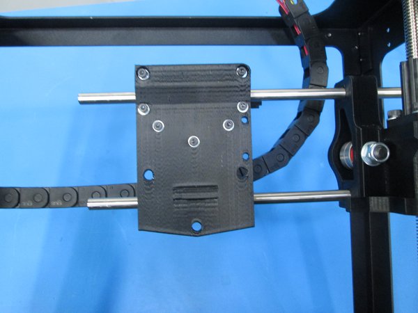
Slide the X carriage onto the rods as shown, noting orientation.
Slide the smooth rods through the X end motor.
Set the smooth rods so there is approximately 2 mm sticking out of the idler end.
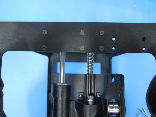
Secure the smooth rods with 4x M3x6 set screws as shown.
Note, the fourth set screw location is under the bunch of wires.
Also, be careful not to over tighten the set screws as it will pull out the insert.
Connect the cable guide to the cable guide connector as shown.
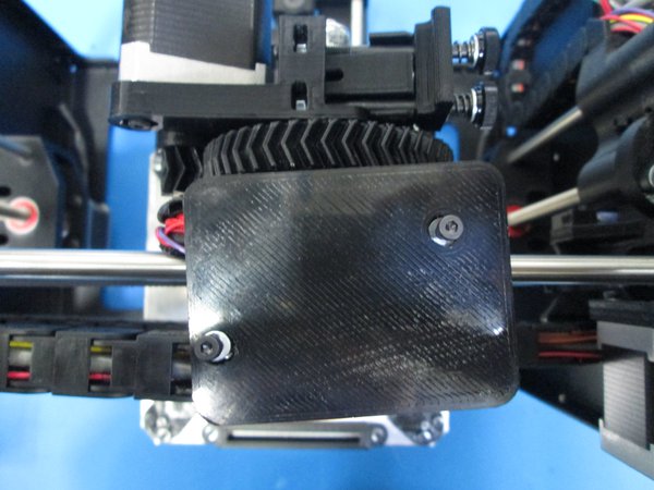
Tighten the 4 screws that hold down the top double bearing on the X carriage.
- Are all 4 set screws installed?
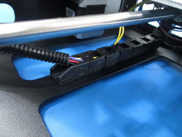
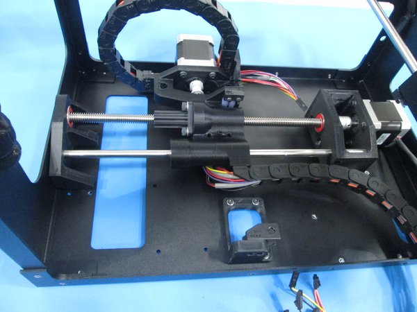
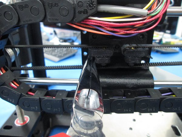
Connect the cable guide to the cable guide connector as shown.
Feed the wires out of the hole to the left.
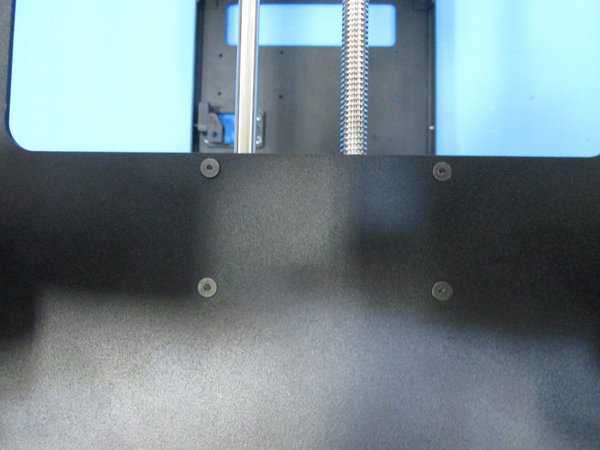
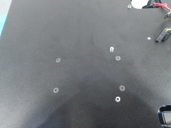
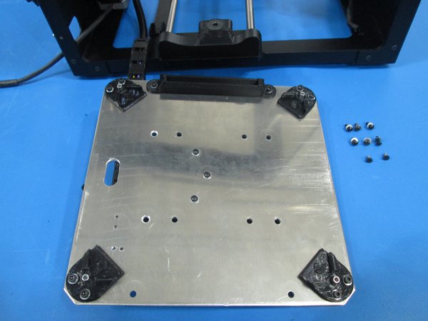
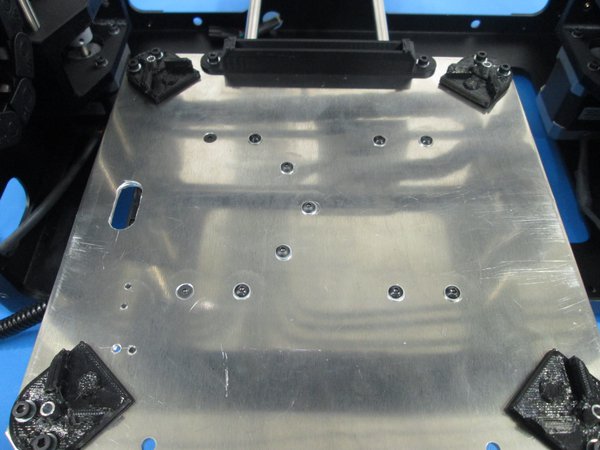
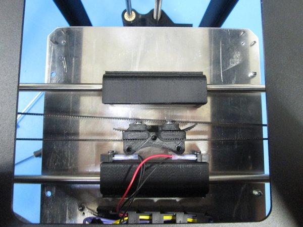
Attach the bed plate to the bearing holders using 2x M3x6 flat head screws and 6x M3x8 BHCS with M3 washers as shown.
The 2x M3x6 flat head screws go into the two recessed holes as shown.
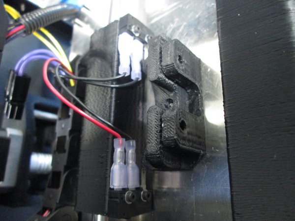
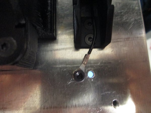
Connect the paired black switch wires to the front limit switch as shown.
Connect the paired red and black wires to the rear limit switch as shown.
Screw the ground wire into the plate using a M3x5 SHCS with star washer. The star washer goes under the ground wire.
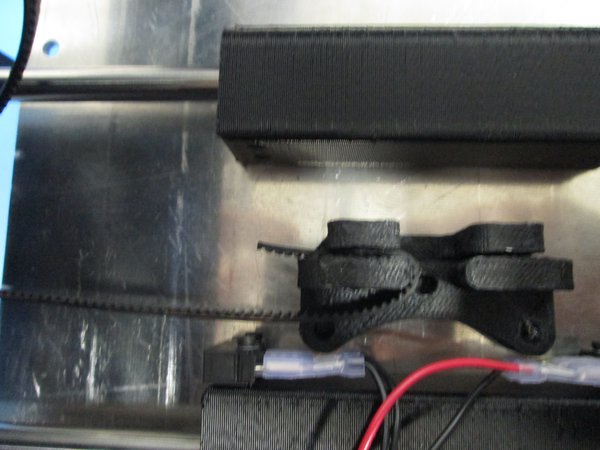
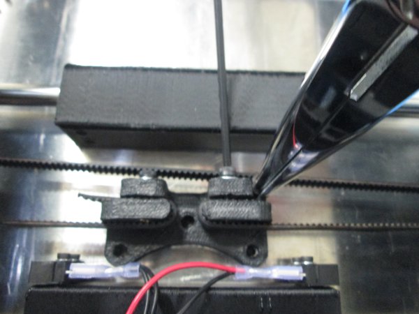
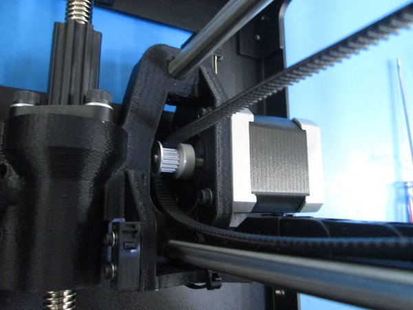
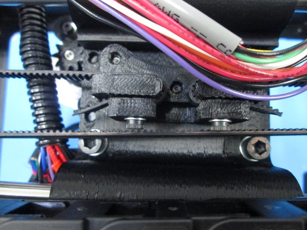
Cut the belt then attach it to the idler end of the belt mount using 1x M3x12 SHCS and M3 washer as shown.
Feed the belt through the idler and around the motor pulley then back into the belt mount as shown.
Tighten the belt with a pair of needle nose pliers and secure with 1x M3x12 SHCS and M3 washer as shown.
Make sure the belt is secure but don't over tighten the belt mount as it may crack.
- Is the belt tight?
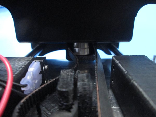
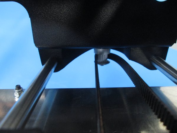
Cut the belt and attach it to the x belt mount using 1x M3x12 SHCS with M3 washer as shown.
Route it around the motor pulley and around the idler.
Attach the belt to the belt mount, tighten with needle nose pliers and secure it with 1x M3x12 SHCS and M3 washer as shown.
Make sure that the belt is secure but don't over tighten the belt mount as it may crack.
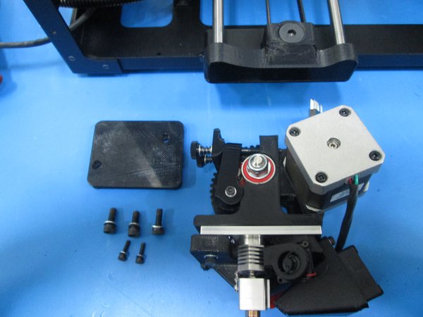
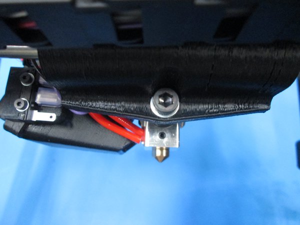
Next, attach the print head using 3x M5x14 SHCS with M5 washers as shown.
Connect the 20 POS connector and cover it with the X carriage cover using 2x M3x12 SHCS and M3 washers.
- Is the belt tight?
- Is the 20 POS connector secure?

- Are the wires tucked in nicely and zip ties secure?
- Complete