Mini Electrical Cover Assembly Workflow
Tools
Components Required
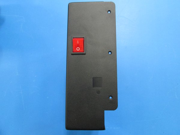
- Electrical cover
- Power supply
- Power switch
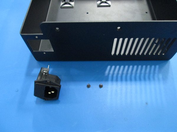
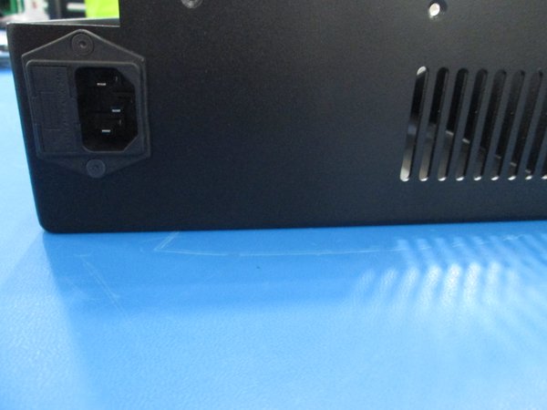
- Power cord receptacle
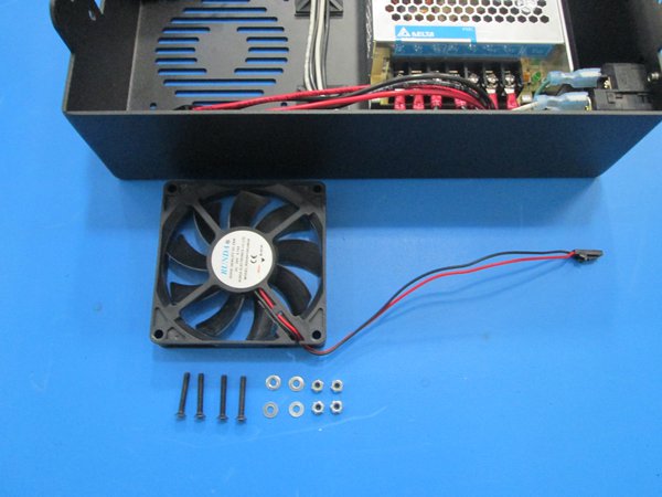
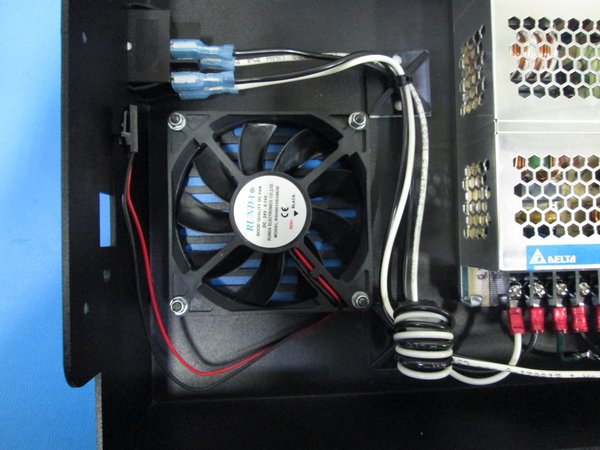
- 80 mm fan
- 4 Pos plug, 200 mm length
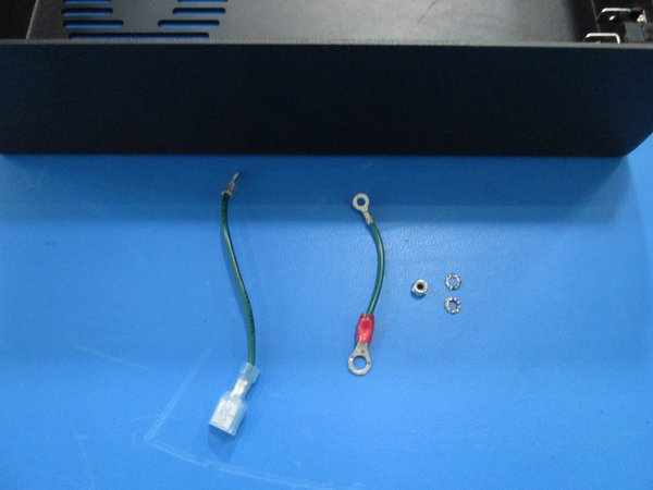
- Green ground wire w/ spade and ground lug, 80 mm length
- Green ground wire w/ two ground lugs, 50 mm length
- White and black wires, 250 mm length
- White and black wires, 320 mm length
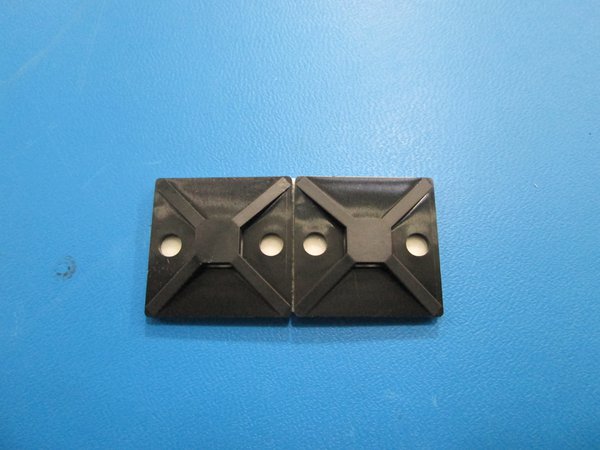
- Zip tie bases
- Zip ties
- M3x6 Flat head screw
- M3x20 Flat head screw
- M3 Nyloc nut
- M3 washer
- M3 star washer
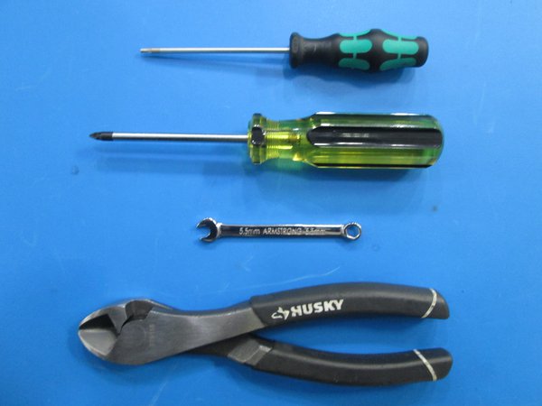
Tools Required
- 2 mm Allen driver
- 5.5 mm wrench
- Phillips screw driver
- Cutters
- Are all the tools and components gathered?
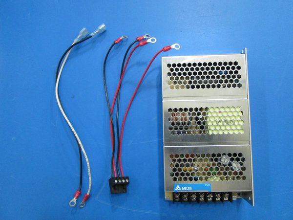
Wires and hardware
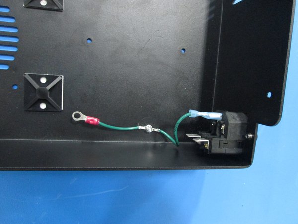
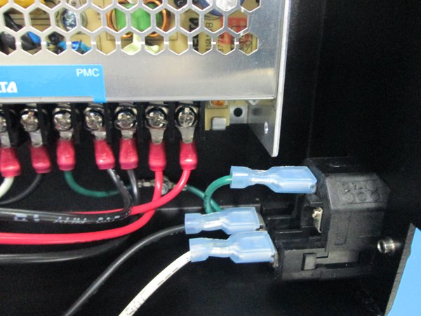
Wires attached, spade connector attached to receptacle
- Did you use star washers and connector the one wire?
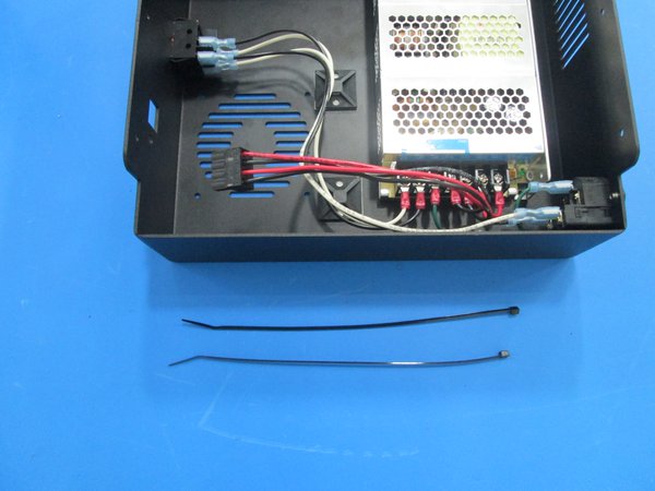
Power supply and wires
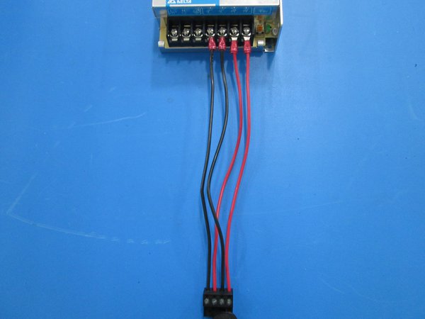
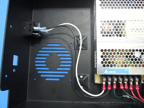
Orientation of 4 pos connector
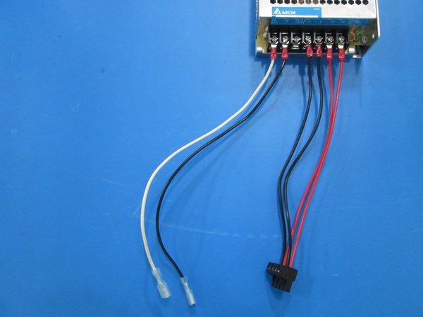
Orientation of 250 mm black and white wires
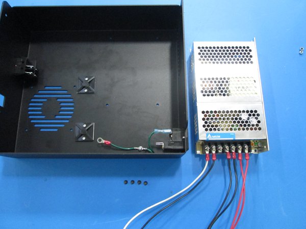
Components
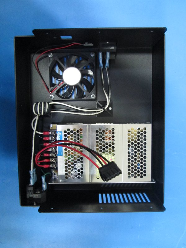
View of screws installed from back
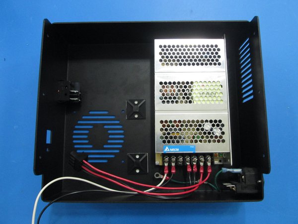
Power supply mounted
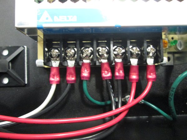
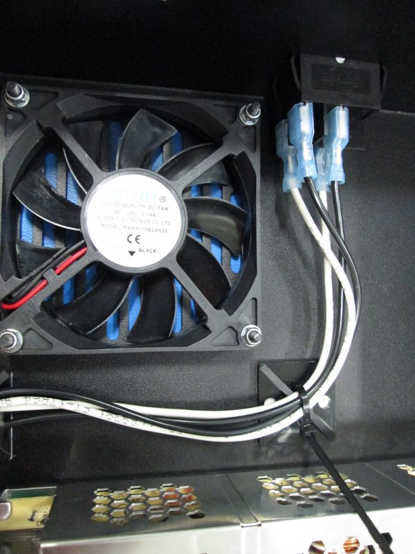
Green ground wire attached
Black and white wires attached, note orientation
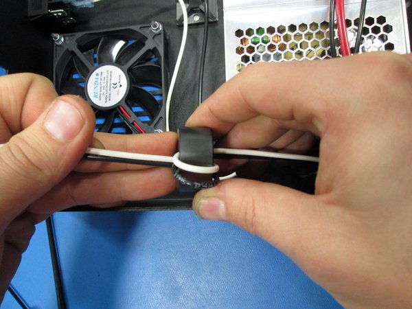
Zip down ferrite.
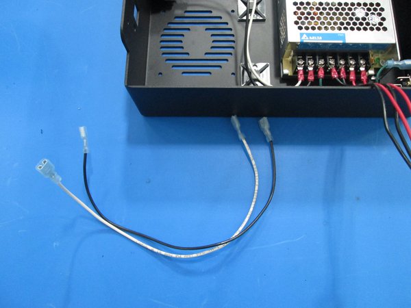
560 mm length wires
Wrap wires around ferrite.
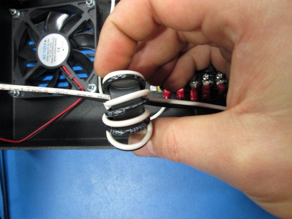
wires wrapped 4 times.
Connected to the plug
Zip ties
Zip tied in place, note the pulled slack
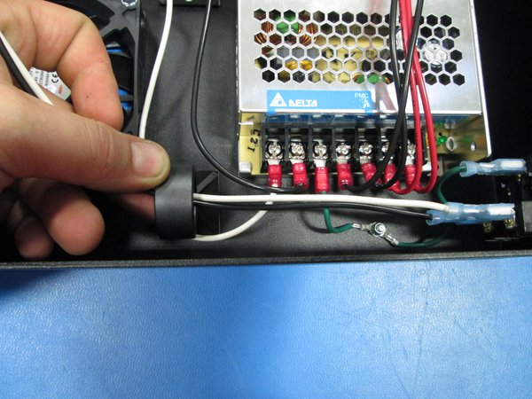
Connect the black and white(560 mm length) wires with the spade connectors from the switch to the plug as shown.
Make sure to wrap the wires four times around the ferrite alternating the wires as shown.
Wrap wires bottom to top.
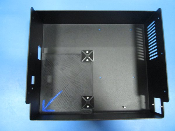
Next, zip tie the four black and white wires to the zip tie bases making sure the slack is pulled and the wires aren't touching the bottom of the case and all the slack is towards the top as shown.
- Are the wires connected and secured properly?